Tamagotchi [in progress]
I’ve always wanted to use my embedded systems knowledge to make something small and contained that I can carry around with me and show off (mainly so I can show relatives what I’m actually learning about at college). I’ve never owned a Tamagotchi, but I am a fan of little guys/trinkets and so this felt like the perfect project to take on. I can exercise my hardware knowledge, while also gaining experience designing an all encompassing product. The plan is to make something polished enough that I can give some to my friends at a low cost, and with relative ease.
Research
When I first embarked on this project, I didn’t really know that much about how the Tamagotchi gameplay loop worked. The only thing I knew was that they could randomly call out for care, and that other than those few moments they didn’t really due much. Rather naively, I decided to start researching which microcontroller to use based off of the simple notion that it would have to go to sleep and wake up intermittently.
Picking the Microcontroller
When I first started thinking about this project, it was first semester freshman year, and while I knew some things about embedded I was still way out of my element. By doing a bit of research, I figured out that in order to fulfill my sleep/wakeup requirements I would likely need a microcontroller with a real time clock (RTC). My initial plans were to make the tamagotchi somewhat bluetooth enabled and so after some investigating I purchased the ESP32-C6. It satisfied my bluetooth requirement while additionally having a RTC and being relatively easy to solder onto a PCB. However, after purchasing a devkit and doing some small projects I quickly got busy with school and let the project fall to the wayside. However, this would turn out to be a blessing in disguise.
By the time I picked the project back up, I was deep into ECE 319: Introduction to Embedded Systems, the perfect pairing for this project. Often in lecture I would connect the concepts we were learning about to ideas I had for my tamagotchi project, and so it was at this point I really started to dive into more research. I had now disregarded the idea of making the tamagotchi bluetooth enabled. While I did think it would be a cool concept, I didn’t really have any idea as to why it should be bluetooth enabled1. As such, I also decided not to use an ESP for the MCU. It was starting to seem too big and too powerful for something I wanted to be small and simple. In my embedded coursework, we were using the TI MSPM0 and it introduced me to the fact that there’s other microcontroller out there that are small, but equally capable as the fancy ESP’s I had heard a lot about. While I didn’t end up going with a TI MCU, I did start to look into STM32 MCU’s and it was here where I really started to dive into the process.
By now I had a pretty well defined list of requirements for the microncontroller. It needed:
- A real time clock that can wakeup the microcontroller from sleep.
- A sleep mode that consumes very little energy.
- An I2C peripheral to drive the display I had my eyes on.
- An easy to solder package.
The STM32 line seemed to be very well documented, maker friendly, and featured a plethora of options, so I decided to focus my search there. Most all of their chips came in the LQFP package, so soldering wouldn’t be too hard to do by hand. Additionally I2C is quite common, so the main thing I had to search for was something low power with an RTC. Luckily, low power applications often use a real time clock so they can wakeup on regular intervals to perform tasks and then go back to sleep, so it didn’t take much searching before I decided on the STM32L010 line. The only other thing to pick out was the amount of onboard memory I wanted, and aiming to avoid memory constraints I went with the STM32L010K8.
Game Research
As I’ve already mentioned, I didn’t really know much about the actual Tamagotchi gameplay itself when I started my work on this project. A lot of my initial hardware prototyping was done before I delved into the research on how I wanted to make the game, but quickly came to a halt as I realized I didn’t really know how I wanted the game to work. However, over the summer I spent some time to take notes on how the original Tamagotchi game worked, and decided to try and replicate it first then change it to be my own. Specifically I watched this video:
Which provided me with a plethora of information on how the original tamagotchi game worked. From this, I designed the characters that you would be able to raise and gave them some basic statistics.

These were the references I used when designing the sprites I ended up making for the monochrome display. The only change I made was making the characters with the longer legs the “better” evolution because I ended up liking them more than the little guys (sorry little guys).
Hardware Prototyping
When I finally decided on the STM32L010K8, I was super excited to purchase a devkit for it and begin experimenting. It was at this point I learned that not every microcontroller has an easy to use devkit made for it. It was at this point I considered switching to a more conventional MCU so I wouldn’t have to make a devkit, but I decided to stick to it and learn about how one goes about making their development board. So I did what any normal person would do and started designing a development board for the STM32L010K8… Is what I would say if I did that.
While I did start designing a PCB, I felt like I was stepping a bit to far out of my element. While I did have some PCB design experience, it was not nearly enough to make me feel confident taking on this project. It was around this time however that I discovered LQFP breakout boards. It seemed so easy, I just solder the chip to the board, and then build the required circuit on a breadboard! The shocking thing is, besides having to learn how to drag solder, using the breakout board actually worked really well. It was also a great moment for me developmentally as an engineer, seeing that you really can just use your knowledge to make any component work.
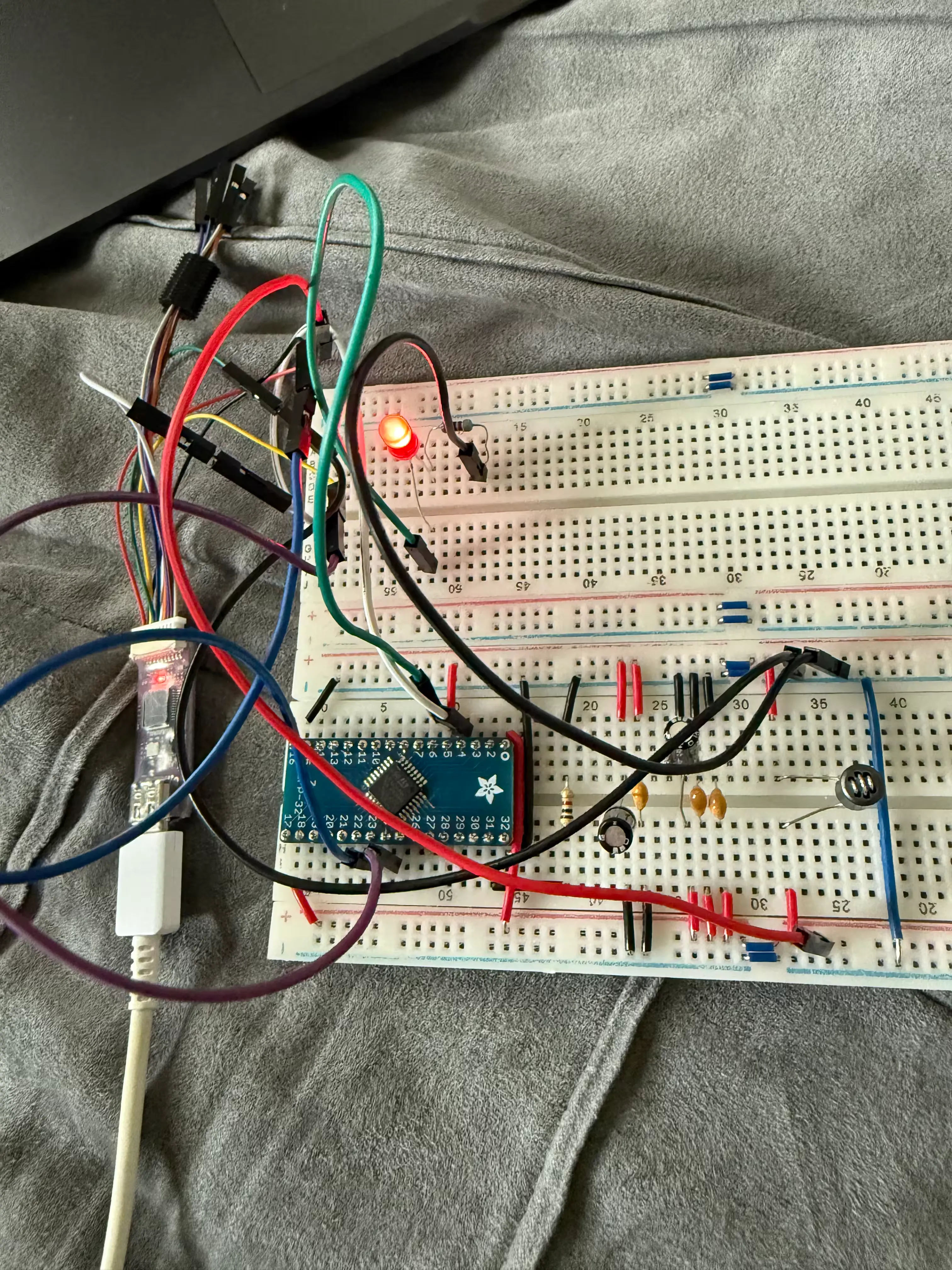
Though it may look messy (the board was currently setup on my bed and I hastily took a picture in my excitement that it was working), it was really rewording to see my own “hardware” running a blink program. The whole project was really riding on this working, and so it was really exciting to see that this could actually work.
From here I started integrating the display that I had picked out and adding buttons to control the rudimentary UI I had up and running. This was done over a long period of time, just working on things as I had time. Most notably was working on the debounce circuit for the buttons, which I did shortly after returning to college since I’d have access to an oscilloscope. Here’s the nice waveforms I was able to get:
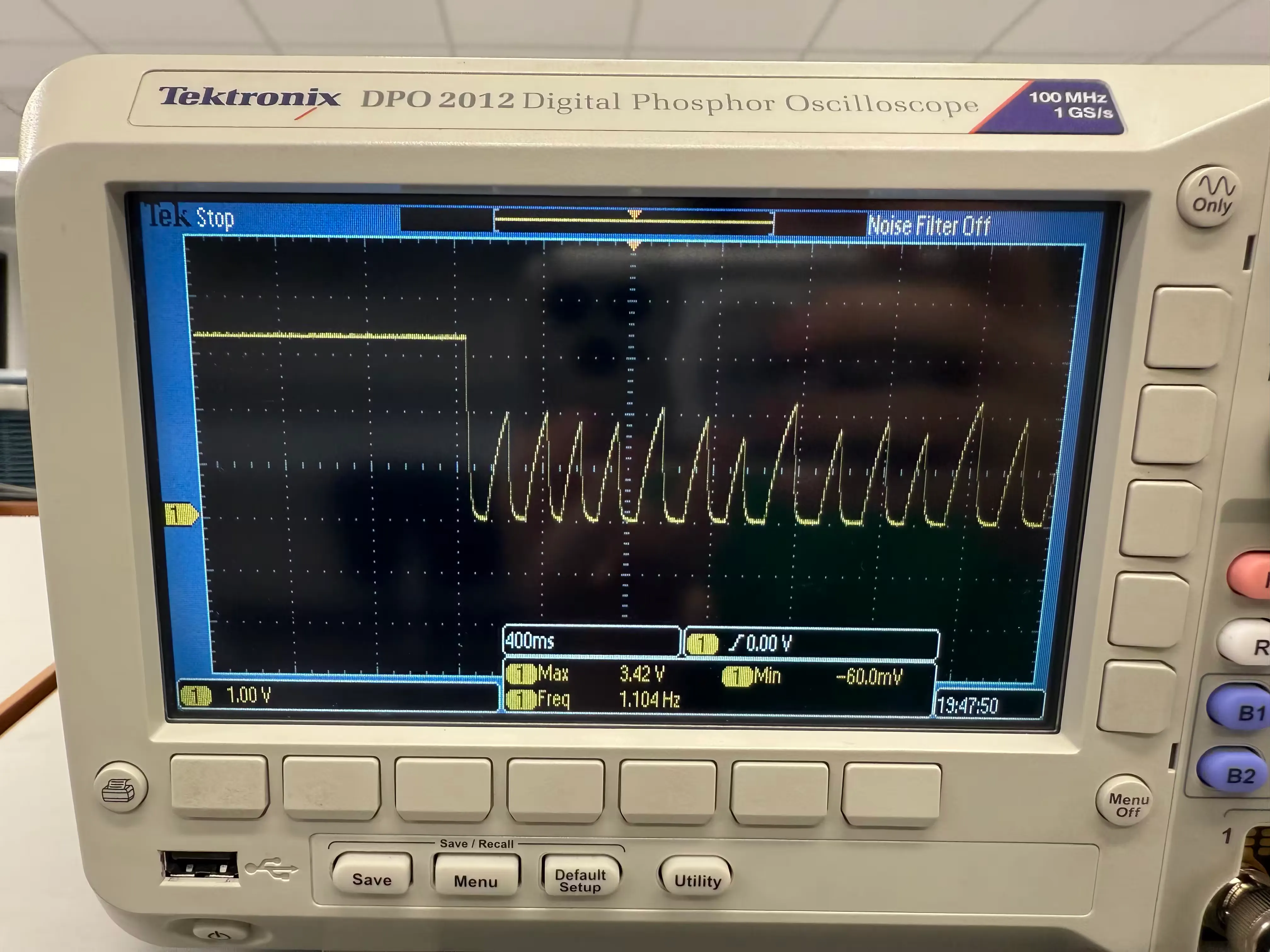
This is the improperly tuned RC circuit. Notice how the circuit takes too long to charge whenever the button is quickly pressed.
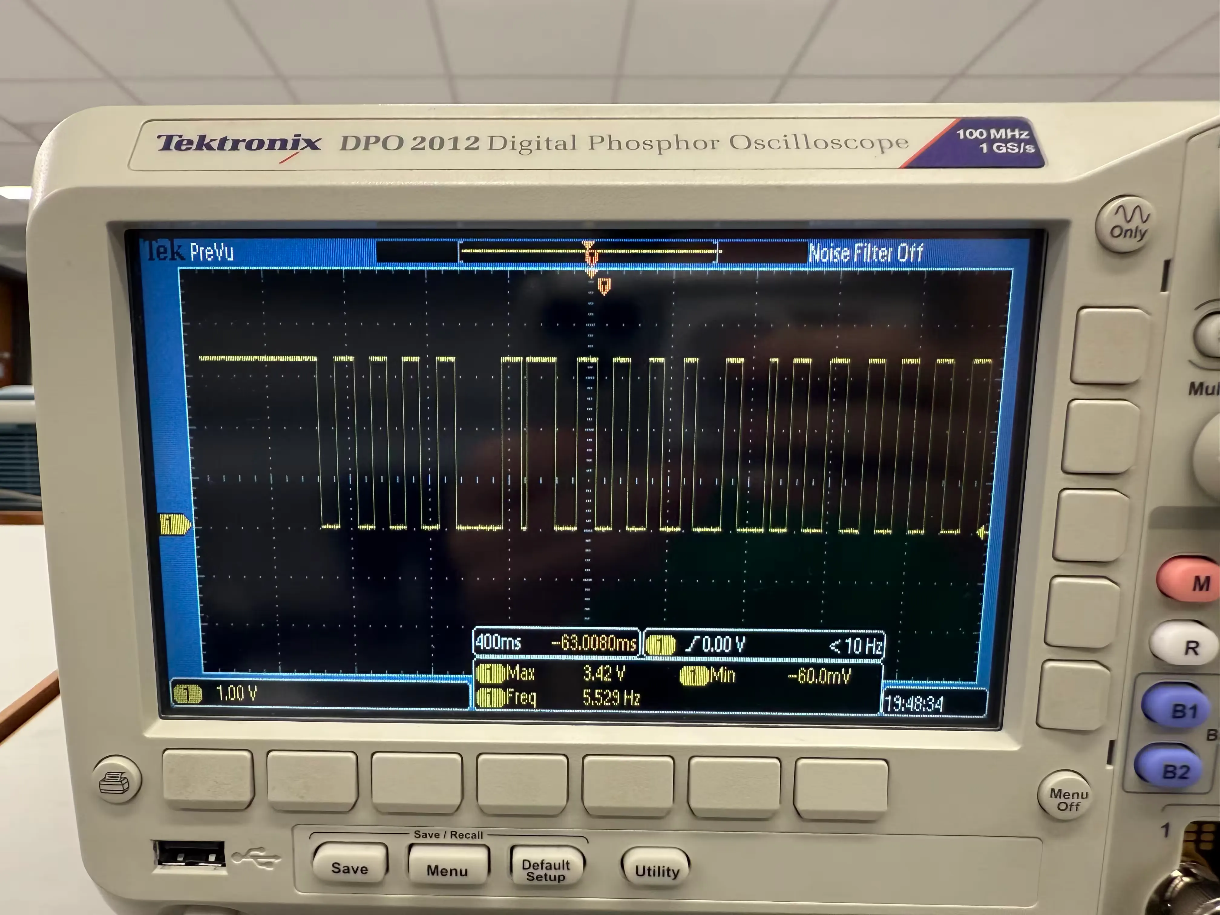
This is the properly tuned RC circuit. It has clean transitions as I press the button as quickly as I can.
The only component I had left to work on was the RTC. However, this is where my
“development board” started to show it’s weaknesses. The oscillators that I
purchased to use with the RTC have really small pins and so I can’t exactly
breadboard with them. While I could solder them to some protoboard and connect
them to the breadboard through that, it seemed like this was a sign I should
probably switch to developing on a proper PCB. Additionally, during my
Making the PCB
This is the part I’m working on right now
The main things I’m working on for the PCB is trying to do all the design decisions that I thought would be too hard to breadboard. This is mostly setting up a proper power scheme and oscillator circuit.
Footnotes
-
You may have noticed I’ve only been referring to this idea as “bluetooth enabled”. The idea never really moved past that phase of just being a broad concept. One thought was that you could use your phone to connect to the tamagotchi and possibly upload custom pets or sprites to the device. Another idea was that maybe it could send you push notifications whenever it needed care. Ultimately though I just wanted this project to be a fun little key chain and adding an app and additional functionality just seemed beyond the point. Maybe one day I’ll do a tamagotchi V2, where I implement an app and bluetooth. ↩